Panelmount Cables and Wall Plates
A Complete Design and Installation Guide
 This guide is meant to give a general overview to
 the process of installing DataPro face plates and
panel-mount cables in a home or office setting. It
is by no means an installation guide, and all
installing should be done by a licensed technician.
- Running the Wiring
- Installing the Wall Plates
- Mounting the Cables
- Finishing Touches
- Boosting USB Signals
- FireWire and DVI Limitations
- Using Spliced VGA Cables
Back to the Plates & Cables Home
RUNNING THE WIRING
Depending on the length and location of your run, getting the cabling end to end can be a five-minute or all-day job. Try to minimize the number of turns and drill holes by locating plates between the same studs or nearby existing wiring plates (i.e. phone lines).
For USB cables, which run only 15 feet and must be connected to booster cables, it is best to secure the splices with tape or other adhesive. USB cables do not have mating screws and might disconnect during the installation or later on. Read more for information on extended USB runs.
For VGA cables, the best method is a spliced (non-terminated) cable that runs through a hole much smaller than the VGA hood. We stock a full line of non-terminated VGA cables ideal for installations. It is strongly recommended that these cables are pulled with a lead and not directly from the round 8-pin Din connector, as this may strain the wires and could potentially damage the cable. Read more for information on non-term and spliced VGA cables.
INSTALLING THE WALL PLATES

There are five basic methods for mounting our standard wall plates, depending on the surface and type of connection. The simplest is just the plate itself, which can be mounted with screws directly into a solid supportive wall like wood or metal.
For less structural surfaces, like plaster or drywall, a mounting bracket is recommended to strengthen the attachment points. When affixing a mounting bracket to a wall, finding a stud is not required—simply cut a hole, slip the bracket in place, and tighten the wing clamps. These non-conductive plastic frames are durable and easy to install, adjustable for mounting in a surface between 1/4" and 1" thick. The face plate can then be mounted to the bracket for a strong, sturdy connection.
The next great mounting option is accomplished by using a in-wall mounting box. This durable box must be screwed to a stud, which provides a structurally stable in-wall enclosure. When affixing a box, one must first find a stud then cut an opening adjoining the stud, slip the box in place and secure with screws. The advantages to using the box include: you can mate the box to standard electrical conduit; your wire terminations will always be conveniently available within the box; and a box screwed to a stud is the most secure mounting.
For surfaces which are difficult to drill or cut into, such as concrete or brick, a surface-mount box provides a clean solution. These can mount onto the wall with screws or the provided adhesive, and a standard face plate can attach directly to the front. They provide an inch and a half of clearance for connectors behind the plate, and cables can be run through the gap in the back or through a hole drilled into the plastic sides.
Keystone connectors can also be used in smaller keystone surface boxes that are a discreet way to add network and phone connections without installing additional plates. At only and inch high and just over two inches deep, we offer one-port and two-port boxes that can be customized with any of our Keystone compatible connectors.
MOUNTING THE CABLES
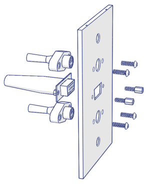
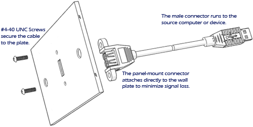
All of our panel-mount and mountable cables are designed for an easy, no-hassle connection to the plates. Every panel-mount cable includes mounting screws that match the cutout on the plates, and attach directly in a matter of seconds. Cables that have mating screws, such as VGA and DVI, are provided with hex-nut screws that also attach through the holes in the plate, to allow the external cables to screw in securely. If you are using Keystone connectors, they easily snap into the Keystone plug on the plate and receive the matching wire on the inside.
If you choose not to purchase a panel-mount or mountable cable, or already have existing terminated cables that you would like to mount, it is also possible to attach couplers into the face plates for a slim splice. We strongly discourage the use of couplers, because every connection causes signal loss and noise interference, especially on high-throughput signals like VGA, USB, and DVI.

FINISHING TOUCHES
To complete the cable installation, first make sure to test all wiring before securing the plates and putting tools away. Internal connections that don't have mating screws, like USB, should be taped or otherwise secured to prevent slippage. Self-terminated plugs should always be tested before the plates are fully installed.And although some connectors (like RJ11, CAT5e, and RCA) are offered in a variety of colors, others (like USB, PS2, and VGA) are not, and having multiple ports on the same plate can be confusing. It is often a good idea to identify the ports with some form of adhesive label or diagram.
BOOSTING USB SIGNALS
One of the biggest obstacles encountered in planning a wire run is the signal limitation of Universal Serial Bus (USB). With a maximum guaranteed length of only 16 feet, very few USB runs are successful without the use of Active USB Booster Cables. These are extension cables which feature a booster-box on the female end that refreshes the USB output, providing and additional 15 feet of signal. These extensions are chainable, and when strung together can achieve a new maximum of up to 80 feet. Without the use of boosters, we have successfully run USB up to 31 feet, but only with high-grade devices. With lower quality products, we've lost signal at less than 20 feet.The first key to effective design is to make sure that, over the span of your whole run, there is never any stretch of cable over 16 feet. This means from computer to booster, booster to booster, and booster to device; each should be no more than 16 feet. The other crucial element of effective design is to be aware that the female end of the active booster, which houses the booster box, must be on the device side of the run, with the male end pointing towards the computer. Because these are powered from the computer's USB controller, they will not function when oriented the other way.
FIREWIRE AND DVI LIMITATIONS
Unfortunately, USB is not the only type of cable with signal limitations. FireWire and DVI also suffer from the 16 foot maximum, and are harder to extend than USB. With strong devices, FireWire has been known to run longer, but is not guaranteed. DVI is much less reliable at even 30 feet, and requires more expensive solutions.FireWire boosting is possible through the use of FireWire repeater cables, which offer the convenience and low cost of inline booster cables, but are still highly effective. Our in-house tests have successfully run over one hundred feet with a single firewire booster cable, but individual results may vary.
DVI has a specified digital maximum of 20 feet, although like USB and FireWire, this is an elastic number and can often work at twice that (with good equipment). For longer range runs, extending even further is possible through the use of inline boosters. These are not booster cables like USB has, but rather externally powered repeater boxes. Because they require a power supply, these are less convenient to install, and are also quite expensive.
The cheapest way to extend DVI is to use an analog signal, from DVI-A or DVI-I, and convert it to VGA. High-grade coax VGA wire can run over 200 feet with only minimal loss, but you will sacrifice the benefits of the digital video signal.
If you'd like to maintain a digital video signal for a longer run, the best method is to use an inline DVI repeater booster. This is a small powered box that will clean and amplify an incoming DVI signal for strong image fidelity at up to 75 feet. Because it requires an external power supply, this solution is not always the most feasible, but it is the only reliable way to maintain a fully digital signal at long lengths.
USING SPLICED VGA CABLES
For video installations, we recommend using DVI for any run under 16 feet and VGA for any run above that. Our VGA wires all use mini-coaxial cables to maximize shielding and prevent noise and ghosting up to and over 200 feet, and are available in custom lengths for just what you need.For improved flexibility, we built special VGA cables in a non-terminated fashion so that the wire can be run through holes smaller than a VGA connector. Using an 8-pin Din splice, our Non-Term cables slip easily through holes just 5/8" in diameter, and terminating crimp-pins is not required. When the length of wire has been pulled, the spliced end is matched with a VGA pigtail of the appropriate gender, and the installation is complete. Available in any length and any gender combination.
Unauthorized duplication strictly prohibited.


